
How to Choose BLDC Motors for Robots and Arms
A recent analysis from The Robot Report outlines the critical mechanical and electrical factors engineers must weigh when selecting brushless DC motors for mobile platforms and robotic joints.
 Radwan AbdulhadiEditor and technology writer
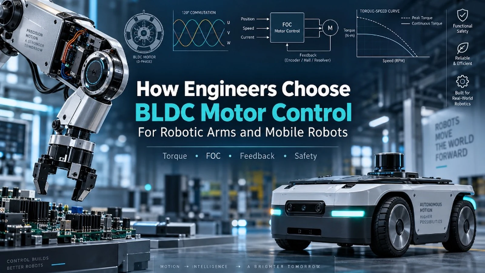
Understanding Mechanical Requirements and System Design
Selecting a brushless DC, or BLDC, motor for robotic arms or mobile robots starts with the mechanical system, rather than simply browsing a controller catalog. A motor rated for a specific voltage and wattage does not automatically indicate whether it can deliver required low-speed torque, regulate position accurately, absorb regenerative energy, or survive harsh thermal duty cycles.
Engineers building a robotic actuator must view the entire system as a cohesive unit. The motor, inverter, current sensors, rotor position feedback, gearbox, brake, output encoder, thermal path, communications interface, and higher-level robot software all influence the final performance of the actuator.
Differentiating Industrial Arms from Mobile Platforms
Different robotic applications impose distinct performance priorities. An industrial or collaborative robotic arm joint generally prioritizes controllable torque, low-speed smoothness, position accuracy, collision response, backdrivability, and thermal performance.
In contrast, a mobile robot drive motor places much more emphasis on efficiency, starting torque, braking, traction, battery utilization, speed regulation, and synchronization between drive channels. Furthermore, commercial robotics literature often uses the terms BLDC and PMSM interchangeably because both are three-phase permanent-magnet machines driven by electronic inverters. Companies like STMicroelectronics treat three-phase BLDC and PMSM control as related application areas.
Evaluating Mechanical Load and Regenerative Energy
The initial selection exercise requires establishing what the motor must actually accomplish under real operating conditions. For robotic arms, load calculations must account for link inertia, payload, gravity compensation, gearbox ratio, backlash, compliance, counterbalance, and encoder location. A motor-side encoder can report rotor position accurately even when the joint output contains transmission error.
For mobile robots, the analysis starts with vehicle mass, wheel radius, rolling resistance, slope, acceleration, terrain, wheel slip, and drive configuration. Differential-drive platforms demand different synchronization protocols compared to four-wheel-drive vehicles. An outdoor uncrewed ground vehicle (UGV) can spend significantly more time operating under heavy loads than a lightweight indoor delivery robot.
Regenerative energy also demands careful attention. During deceleration or downhill travel, the motor can return energy to the DC bus. The battery, controller, braking strategy, and bus capacitance must all accommodate this energy to prevent over-voltage issues.
Selecting Commutation Methods for Motion Quality
Six-step, sinusoidal, and field-oriented controls serve different operational needs. Six-step or trapezoidal commutation switches the inverter through six electrical states based on rotor position. It is attractive where cost and implementation simplicity matter, or when torque ripple is acceptable, and works well when a motor spends most of its time at moderate or high speeds.
Field-oriented control (FOC) takes the control process further by transforming measured phase currents into a rotating reference frame via Clarke and Park transformations. Texas Instruments provides motor control reference material illustrating this practical structure with PI regulators, position and speed loops, and space vector PWM. FOC is frequently a natural fit for applications requiring smooth low-speed motion, fast torque response, and accurate speed regulation.
The Critical Role of Feedback Selection
Feedback selection is just as vital as the chosen commutation algorithm. Hall effect sensors, incremental encoders, absolute magnetic encoders, optical encoders, resolvers, and sensorless estimation each address distinct engineering hurdles.
While Hall sensors provide coarse rotor position information suitable for cost-sensitive mobile platforms, incremental and absolute encoders offer the higher fidelity needed for precise servo control and immediate startup position awareness without h
Sources
- The Robot ReportHow to choose a BLDC motor for robotic arms and mobile robots
Continue chronologically


Related stories
What AgTech Founders Get Wrong About ROI in Agriculture
Farmhand Ventures founding general partner Connie Bowen discusses return on investment challenges and the future of work in agricultural technology.

2026 Robotics Handbook Explores Humanoids and AI
The 2026 Robotics Handbook examines humanoid robots, artificial intelligence, dexterous manipulation, and automation trends in construction.

Nominations Open for 2027 TRR50 Robotics Innovation Awards
Nominations are open for the 2027 TRR50 Robotics Innovation Awards, with winners to be honored at the Robotics Summit & Expo in Boston.

Why Humanoid Robot Demos Still Fail the Generalization Test
Explore why impressive humanoid robot demonstrations often fail to generalize, and discover how better data and human judgment help bridge the gap.